
SQL to MODBUS: Send data from a SQL database to MODBUS
Problem scenario:
My goal is to write data from my database to PLC using MODBUS.
Requirements:
- Data Logger Suite Enterprise or a trial version. This logger can work with MODBUS RTU and TCP at the same time.
It is assumed that:
You have configured the communication settings on the device:
- MODBUS TCP - IP address, Subnet, Gateway. You must assign a static IP address for the device.
- MODBUS RTU - baud rate and the number of data bits.
Solution:
1. Create a new configuration from the main window using the "Green Plus" button. (fig. 1). You usually need to select the "TCP/IP" interface type for MODBUS TCP and "RS232" for MODBUS RTU. This example shows the connection settings for MODBUS TCP. If your device uses MODBUS RTU, look here. If you've already configured the connection, then go to step #2.
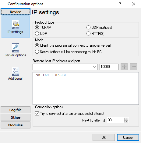
Fig. 1: IP connection settings
2. Go to the "Modules - Query Parser Filter" page. Select the "MODBUS TCP" or "MODBUS RTU" plugin from lists. Then click the "Setup" button.
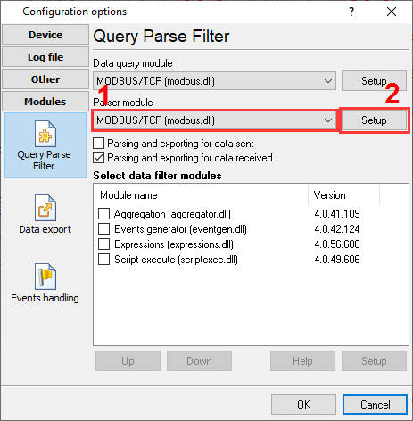
Fig. 2: Selecting the MODBUS plugin
3. Click "Action - Add request" and add new requests to write data (fig. 3-5).
3.1. Set the correct function code. The MODBUS function code should be:
- 6 (Write single register) - if you need to write a value that allocated one MODBUS register in the PLC memory. For example, the value of the data type word, uint16, int16, decimal16.
- 16 (Write multiple registers) - if you need to write larger values (dword, uint32, int32, decimal32, float, etc.).
3.2. The number of registers:
- word, int16, unt16 - one MODBUS registers (2 bytes).
- dword, int32, uint32, float - two registers (4 bytes).
- int64, double precision float - four registers (8 bytes).
3.3. The MODBUS address does not matter. The plugin will receive it from a database.
3.4. Select the "Event" request method. Then specify the event identifier like "WRITE-INT," "WRITE-FLOAT," "WRITE-UINT16". You may use other identifiers but should change them in the next steps too.
Note: You should add a separate request with a different event ID for each data type. For example, one request writes "int" values, another one "float" values.
3.5. Add only one response item to each request with the "VALUE" name.
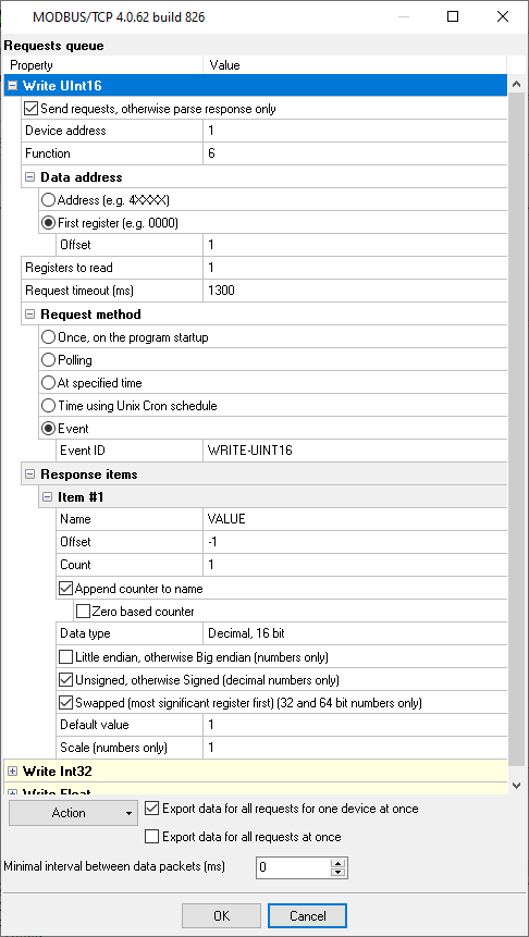
Fig. 3: Adding the "Write" request
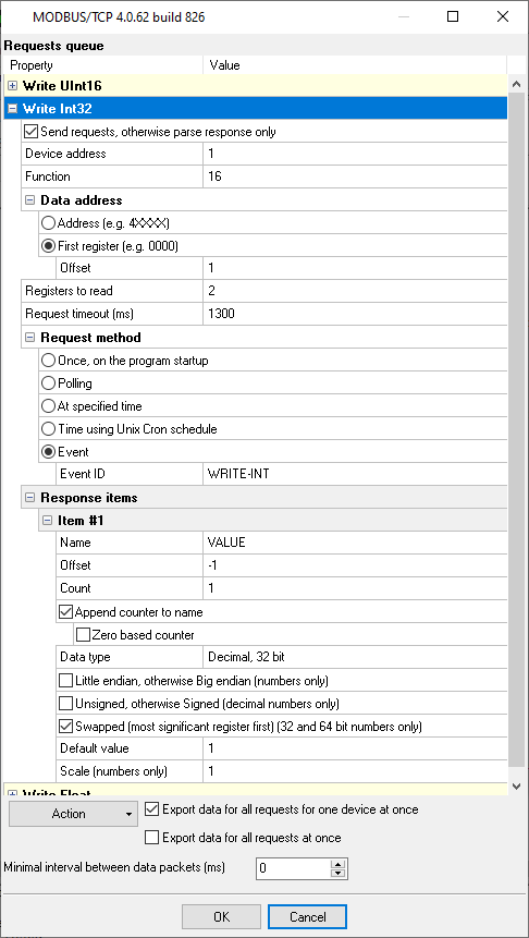
Fig. 4: Writing Int32
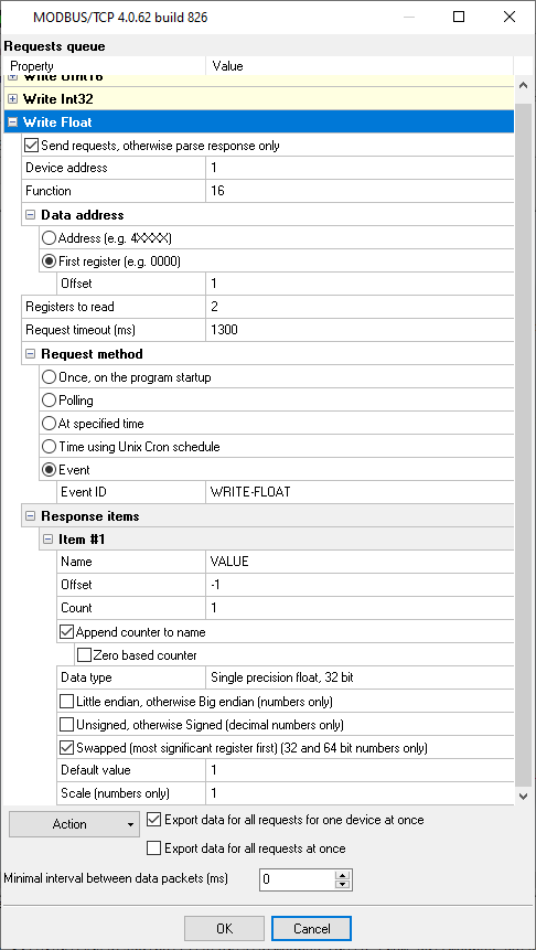
Fig. 5: Writing Float
4. Prepare a table in your SQL database. You may use the following prototypes. The table will contain one row for each register. The "DATE_TIME_STAMP" column specifies the time when the value is changed last time. The logger will use this column to read updates from the table.
Below you can find some table-creating scripts that we recommend to use.
            CREATE TABLE [dbo].[MODBUS_DATA_WRITE](
	[ID] [decimal](10, 0) IDENTITY(1,1) NOT NULL,
	[DATE_TIME_STAMP] [datetime] NULL DEFAULT (getdate()),
	[DATA_SOURCE] [nvarchar](32) NOT NULL,
	[DEVICE_ID] [int] NOT NULL,
	[OFFSET] [int] NULL,
	[VALUE1] [int] NULL,
	[VALUE2] [float] NULL,
	[VALUE3] [smallint] NULL
 CONSTRAINT [PK_MODBUS_DATA_WRITE] PRIMARY KEY CLUSTERED
(
	[ID] ASC
)WITH (IGNORE_DUP_KEY = OFF) ON [PRIMARY]
) ON [PRIMARY]

GO

CREATE TRIGGER dbo.MODBUS_DATA_WRITE_TRIGGER
ON dbo.MODBUS_DATA_WRITE
AFTER UPDATE
AS BEGIN
   SET NOCOUNT ON
   UPDATE dbo.MODBUS_DATA_WRITE
   SET DATE_TIME_STAMP = GETDATE()
   FROM INSERTED
   WHERE INSERTED.ID = MODBUS_DATA_WRITE.ID
END
GO
            CREATE TABLE `MODBUS_DATA_WRITE` (
 `ID` int(11) NOT NULL auto_increment,
 `DATE_TIME_STAMP` DATETIME NULL,
 `DATA_SOURCE_NAME` VARCHAR(32) NOT NULL,
 `DEVICE_ID` INTEGER NOT NULL,
 `OFFSET` INTEGER NULL,
 `VALUE1` INTEGER NULL,
 `VALUE2` DOUBLE NULL,
 `VALUE3` INTEGER NULL,
  PRIMARY KEY  (`ID`)
) ENGINE=InnoDB;

CREATE TRIGGER MODBUS_DATA_WRITE_BI BEFORE INSERT ON `MODBUS_DATA_WRITE`
    FOR EACH ROW SET NEW.DATE_TIME_STAMP = IFNULL(NEW.DATE_TIME_STAMP, NOW());

CREATE TRIGGER MODBUS_DATA_WRITE_BU BEFORE UPDATE ON `MODBUS_DATA_WRITE`
    FOR EACH ROW SET NEW.DATE_TIME_STAMP = IFNULL(NEW.DATE_TIME_STAMP, NOW());
            CREATE TABLE "MODBUS_DATA_WRITE" (
  "ID" SERIAL,
  "DATE_TIME_STAMP" timestamp DEFAULT NULL,
  "DATA_SOURCE_NAME" varchar(32) NOT NULL,
  "DEVICE_ID" integer NOT NULL,
  "OFFSET" integer NULL,
  "VALUE1" integer NULL,
  "VALUE2" real NULL,
  "VALUE3" integer NULL,
  PRIMARY KEY ("ID")
);

CREATE OR REPLACE FUNCTION MODBUS_DATA_WRITE_BI_TRIGGER()
  RETURNS trigger AS
$BODY$
BEGIN
 NEW.DATE_TIME_STAMP := COALESCE(NEW.DATE_TIME_STAMP, NOW());
 RETURN NEW;
END;
$BODY$ LANGUAGE plpgsql;

CREATE TRIGGER MODBUS_DATA_WRITE_BI BEFORE INSERT ON "MODBUS_DATA_WRITE"
    FOR EACH ROW EXECUTE PROCEDURE MODBUS_DATA_WRITE_BI_TRIGGER();

CREATE TRIGGER MODBUS_DATA_WRITE_BU BEFORE UPDATE ON "MODBUS_DATA_WRITE"
    FOR EACH ROW EXECUTE PROCEDURE MODBUS_DATA_WRITE_BI_TRIGGER();
5. Create a new configuration with the SQL interface by clicking the "Green Plus" button in the main window.
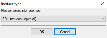
Fig. 6: Adding the SQL data source
6. Configure connection with your database (page #100).
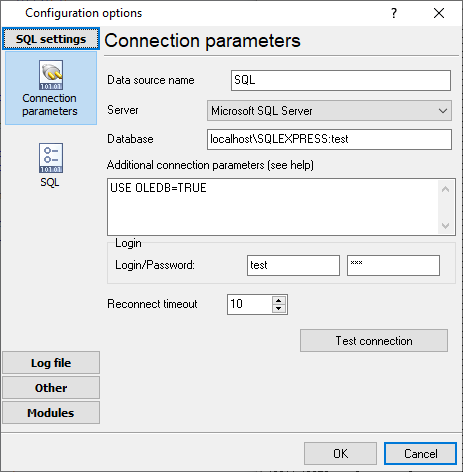
Fig. 7: Database connection settings
7. Specify the name of your database table, the polling interval, and the "DATE_TIME_STAMP" field name.
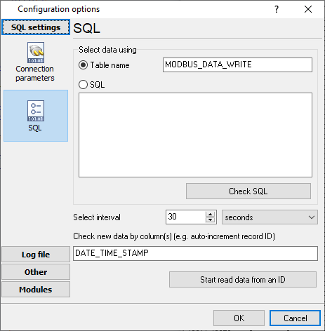
Fig. 8: Database table
When the SQL interface reads data, it appears in the main window.
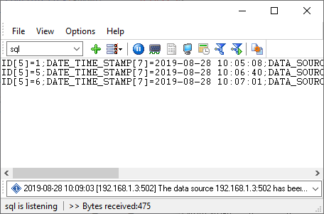
Fig. 9: SQL data
8. Select the "OPC parser" plugin. This plugin does not have any settings.
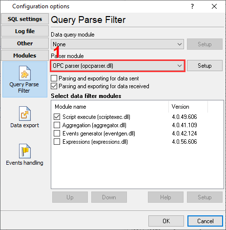
Fig. 10: Parser plugin
9. Script execute - this plugin executes a script and sends values from the database table to the necessary data source (an IP address or an RS232 port), a device, and an address.
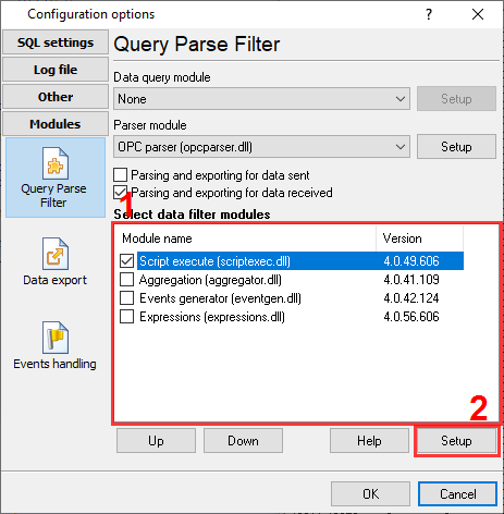
Fig. 11: Script Execute plugin
10. Copy and paste the following script.
            var
 device, addr: integer;
 v1, v2, v3: variant;
 strTargetDataSource: string;
begin
 strTargetDataSource := GetVariable('DATA_SOURCE');
 device := GetVariable('DEVICE_ID'); // MODBUS device ID
 addr := GetVariable('OFFSET'); // MODBUS memory offset
 v1 := GetVariable('VALUE1'); // Int value
 v2 := GetVariable('VALUE2'); // Float value
 v3 := GetVariable('VALUE3'); // UInt16 value

 if VarToStr(v1) <> '' then
   SendEventEx('WRITE-INT', [
   'EVENT-TO-CFG', strTargetDataSource,
   'DEVICE', device,
   'ADDRESS', addr,
   'VALUE', v1
  ]);

 if VarToStr(v2) <> '' then
   SendEventEx('WRITE-FLOAT', [
   'EVENT-TO-CFG', strTargetDataSource,
   'DEVICE', device,
   'ADDRESS', addr,
   'VALUE', v2
  ]);

 if VarToStr(v3) <> '' then
   SendEventEx('WRITE-UINT16', [
   'EVENT-TO-CFG', strTargetDataSource,
   'DEVICE', device,
   'ADDRESS', addr,
   'VALUE', v3
  ]);

end.
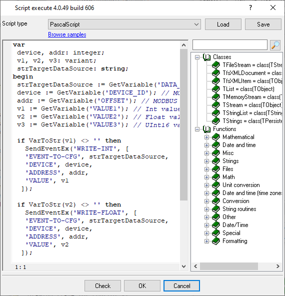
Fig. 12: Script
11. Now, the application works in the following way:
- The SQL interface reads data from a database table.
- The "OPC parser" plugin prepares data for the "Script Execute" plugin.
- The "Script Execute" plugin redirects SQL data to different data sources and devices using events.
- The "MODBUS" plugin in another configuration handles an event, and execute the "write" request.
12. You may execute a SQL statement like the following and insert a new row to the table.
              INSERT INTO MODBUS_DATA_WRITE (DATA_SOURCE, DEVICE_ID, OFFSET, VALUE3)
  VALUES ('192.168.1.3:502', 1, 10, 14321)
You may download the backup copy of this configuration here and restore it from the "File" menu in the main window.
Related articles: SQL to MODBUS: Send data from a SQL database to MODBUS
MODBUS RTU, MODBUS ASCII, MODBUS/TCP
- MODBUS power meter data logging (easy method)
- Sunspec-compatible MODBUS power meters, inverters (easy method)
- MODBUS RTU/TCP polling: Configuring master station (MODBUS RTU, MODBUS TCP, requests, response items).
- MODBUS poll: How to make sure that the application sends requests and receives responses?
- MODBUS poll: How to view register values, not raw MODBUS packets?
- MODBUS polling: How to make sure that the application correctly interprets the responses received from the device?
- MODBUS polling: How to view MODBUS register values in a more easy-to-grasp form (graphs, indicators, etc.)?
- MODBUS: How to combine the data of two requests?
- MODBUS: What is the right way to poll multiple devices?
- Copy settings from Simply MODBUS RTU Master to our Modbus Data Logger.
- Copy settings from the MODBUS Poll utility.
- Controlling PLC coil registers status using MODBUS TCP (MODBUS data parser, custom scripts, events generating, and handling).
- MODBUS to MSSQL: Write MODBUS registers to separate columns
- MODBUS to MySQL: Write MODBUS values to the MySQL database
- MODBUS to a database: Writing MODBUS RTU/TCP values to a database
- MODBUS to a database: Write data to two different tables.
- MODBUS to a database: Write data to two different databases, making a complete copy.
- Sentron PAC 3200: MODBUS TCP Data Logging
- Write data to a MODBUS device
- SQL to MODBUS: Send data from a SQL database to MODBUS.
- MODBUS TCP ↔ MODBUS RTU real-time conversion.
BACNET/IP
IEC 62056-21
- IEC 62056-21 power meter data logging (Iskra Emco, Satec, Landis+Gyr)